


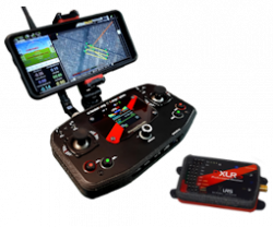

GCSD1A New and economic long-range Ground Control Station, oriented to automatic flights without video. A minimalist and elegant design that will not leave you indifferent.... Continue reading
📧 Contact Us: sales@dmd.es
💬(+34) 615 18 50 77
Return to previous page
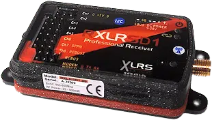
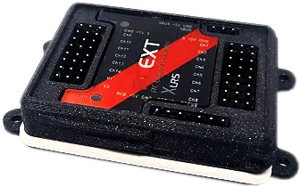
RXLRSD1 | Professional Receiver RC & Telemetry

Ready to work up 25Km or more (LOS)
*Range RC and telemetry max.100Km.
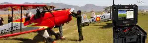
Prepared for any type of vehicles
UAV, VTOL, Dron, UAS, UGV, AGV, UV, Car, Boat, Robots and more…

Radio Specifications
The RXLRSD1 receiver uses the 5th generation XLRS radio frequency module (WMX5H), it is capable of reaching 100Km (LOS) with the right combination of antennas.
Two frequency bands: 313Mhz to 470Mhz and 863Mhz to 950Mhz to choose.
Sensitivity: -110dBm.
Bandwidth (Radio Modem): 100Kb.
Power RF: 500mW, by default. Optionally it can be increased up to 1W.
Excellent frequency stability: +-1ppm.
The frequency, power, sensitivity and modulation are adjustable, normally they are blocked for safety and regulations.
Normative:
They comply with CE regulations for Europe, FCC for America and ETA for India.
The receiver supports operation in various RF bands to adapt to country regulations.
Encryption:
128-bit AES to prevent transmitter spoofing or unauthorized drone takeover.
FHSS Frequency Hopping:
Frequency hopping spread spectrum allows multiple channels to interfere and the system remains immune.
FHSS synchronization recovery: <300ms.
The pseudorandom hopping sequence is encrypted with a 10-digit user code.
Redundancy:
Prepared to connect an additional RXLRSD1 receiver and work in redundant mode in the same frequency band.
Connections

x1 Power supply from 9 to 28Vdc polarized and protected against voltage inversion.
x1 SBUS. Serial connection to servo expansion or autopilot (Configurable from 8-16 servos).
x1 SPPM. PWM connection to servo expansion or autopilot (Configurable from 8-16 servos).
x8 Direct outputs for servos with independent power supply (+5V). Some multifunction. 1.5mSeg +- 500uSeg (100%) standard RC. Configurable up to +-1000uSeg (200%) to increase the servo offset if necessary.
x1 Modem Port. Serial interface for telemetry compatible Mavlink protocol or data link transparent, for autopilot PixHawk, Cube or compatible.
x1 RCBus. Bus connection to XLRS peripherals and for firmware update.
x1 I2C. Bus for sensor and peripheral extensions.
x1 LED Power. Indicates if the device is on.
x1 LED RF. Indicates RF Transmission activity (Telemetry).
x1 LED Link RF. Indicates RF reception activity or link (RC or radio modem data).
x1 SMA-Female connector for RC + Telemetry antenna.
Protections:
All connections, including the antenna are protected against ESD (electrostatic discharge).
Dedicated power connector so it isn’t possible to mix up the power connection and damage the receiver.
Polarity inversion +5V.
Servo output with current and voltage limitation.
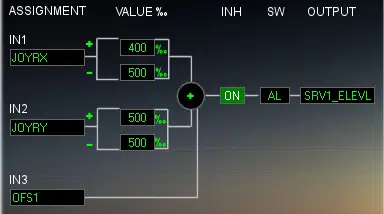
Advanced Mixer in RC Receiver
An advanced RC mixer for professional systems.
The mixes in the xlrs systems are not in the transmitter but in the vehicle part (receiver and servo extenders).
It is different from hobby RC receivers and has many advantages.
Security and error-free. By having the mixes in the receiver there is no possibility of error selecting the different UAV drone models in the transmitter.
It is used to exchange pilots on the fly, with several base stations or portables.
Allows the use of several transmitters with several UAVs without the need to select the model.
The RC transmitter on the ground transmits RAW data (flat, without mixing), so all transmitters are compatible by always transmitting the same data format.
 Different pilots work in different modes (Joystick assignment changes to Throttle, Roll, Pitch and Head), this is not a problem for the XLRS system, it takes less than 10 seconds to change modes on the transmitter but for the receivers there is no problem. no change, everything remains the same. More security since the data sending format from the transmitter does not vary.
It has 8 mixes with 3 inputs.
It has direct assignment of Joysticks to servos
The buttons have an AND function (to increase the safety of an output, two buttons must be pressed at the same time).
Buttons can be filtered with a timer to prevent unwanted button presses and much more.
Even the position value of a servo can be mixed with anything else.
Channels and Servos
XLRS receivers don’t work like most. There is much more inside.
There are no “channels” of servos and you are not limited to just 16 channels or servos, you can actually control many actuators, servos, lights, relays, etc.
The explanation is that 16 channels of servos are not sent from the transmitter.
The raw data of all the Joysticks, potentiometers, sliders, encoders, buttons, switches and switches that the station has is sent.
In total the transmitter sends all this:
• 4 Joysticks x 2 axes each
• 4 Encoders
• 4 Sliders or potentiometers.
• 80 Buttons and SW (Switchs)
And the receiver or each extender processes and mixes it.
All these tickets are usually divided into two, for pilot and co-pilot or observer.
One receiver will control up to 16 servo outputs.
The 16 servos are sent via SBUS, SPPM normally to the autopilot.
There are 8 physical servo outputs that can be reassigned to any of the 16 servos and in some cases are multifunction (voltmeter, rpm, etc.).

Servos, Joysticks, encoders, switches and buttons can be sent via CANBUS.
CANBUS data can be read and sent by telemetry to the base station.
Receiver Extensions
Many more servos can be controlled by adding extenders.
 Each extender has its own separate mixes, digital power outputs, and servos.
Receivers can be expanded by connecting them to:
• Market standard servo extenders.
• CAM8. 8 analog camera switcher + 8 additional servo outputs with own mix.
• RCEXT. extender.
• CAN-BUS. In preparation.
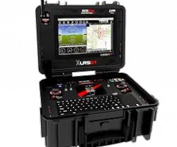
Customized projects
Depending on the project and quantity, we can manufacture customized GCS, if you are interested contact us sales@dmd.es.
Blog XLRSD1

The update of the Data Link V1 to V2 brings many improvements. The box stands out, somewhat larger and better prepared than the previous one, new... Continue reading

2022 comes with many new features for the D1 line. In this article we will review the D1 product changes and the new products. More... Continue reading

2022 comes with a lot of news for the XLRSD1 line. New XPAD1 is a small Radio Control (RC) + Telemetry transmitter, but no less... Continue reading