


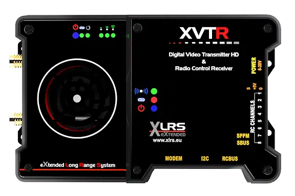
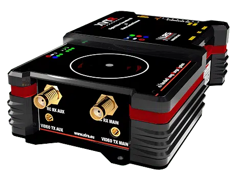
The new XVTR is a powerful Radio Control and Telemetry receiver combined with a latest generation Full HD video transmitter in a single box and already connected internally.
RC Receiver RXLRSV2
The RC receiver is diversity with a 6th Generation radio frequency module and is capable of reaching more than 250Km LOS with the appropriate combination of antennas.
Two frequency bands: from 313Mhz to 470Mhz and from 863Mhz to 950Mhz to choose from.
Dedicated power connector so it is not possible to mix up the power connection and damage the receiver.
They comply with CE regulations for Europe, FCC for America and ETA for India.
The receiver supports operation in various RF bands to adapt to country regulations.
 128-bit AES encryption to prevent transmitter spoofing or unauthorized drone takeover.
FHSS, Frequency Hopping Spread Spectrum, allows multiple channels to interfere and the system remains immune.
The RF (radio) system works on a network, with 32-bit IP addressing similar to that of the Internet. This allows you to select networks and sub networks for your fleet of drones or UAVs.
Prepared to connect an additional receiver and work in diversity x 2 and redundant mode in two different bands or in the same one. This makes it more immune to interference on one band.
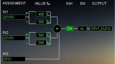
Mixer on RC Receiver
An advanced mixer for professional systems.
The mixes in the xlrs systems are not in the transmitter but in the vehicle part (receiver and servo extenders).
 It is different from hobby RC receivers and has many advantages.
Security and error-free.
By having the mixes in the receiver there is no possibility of error selecting the different UAV drone models in the transmitter.
It is used to exchange pilots on the fly, with several base stations or portables.
Allows the use of several transmitters with several UAVs without the need to select the model.
Channels and Servos
XLRS receivers don’t work like most. There is much more inside. There are no “channels” of servos and you are not limited to just 16 channels or servos, you
can actually control many actuators, servos, lights, relays, etc.
16 servos are sent by SBUS, SPPM to the autopilot.
There are 8 physical servo outputs that can be reassigned to any of the 16 servos and in some cases are multifunction (voltmeter, rpm, etc.).
Extensions receiver:
Many more servos can be controlled by adding extenders.
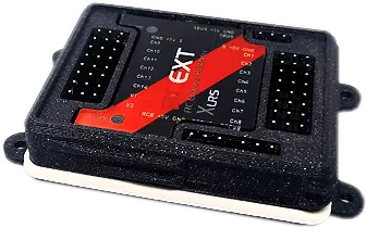 Each extender has its own separate mixes, digital power outputs, and servos.
Receivers can be expanded by connecting them to:
• market standard servo extenders by SPPM
or PWM.
• CAM8. Switcher of 8 analog cameras +8 additional self-mixing servo outputs.
• RCEXT. extender
• CAN-BUS. In preparation.
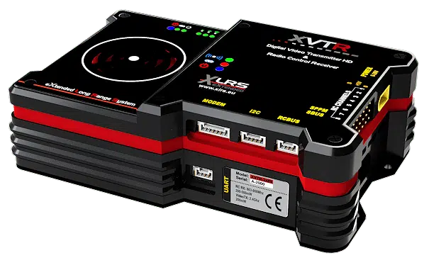
Connections
• 1 Power supply from 9 to 28Vdc polarized and protected against voltage inversion.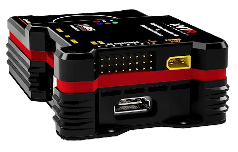
• 2 Sma connectors for RC + telemetry antennas.
• Serial interface for Telemetry compatible Mavlink or transparent for autopilot PixHawk or compatible.
• 8 direct outputs for servos with independent power supply. Some multifunction.
• 1 SBUS. Serial connection to servo expansion or autopilot.
• 1 SPPM. PWM connection to servo expansion or autopilot.
• 1 RCBus. Bus connection to XLRS peripherals and for firmware update.
• 1 I2C. Bus for sensor and peripheral extensions.
• CANBUS (in preparation)
• HDMI video input
• 2 MMCX video antenna outputs at 2.4Ghz
Video Transmitter:
The Long Range Full HD Video Transmitter sends H.265 compressed video at 2.4Ghz with low latency OFDM modulation (200mSeg).
By default it works with FHSS or frequency hopping although it can be configured with a fixed frequency.
The bandwidth is variable and goes from 3 to 20Mhz.
For NLOS flights, a repeater can be used (consult).
The video input is standard HDMI.
Multiple cameras can be used, selecting one at a time, using the CAM8HD camera selector (in preparation).
It has an auxiliary UART (serial port).
It uses two antennas with MMCX connector.
Regulations: CE, FCC.
Range:
The range depends on the combination of antennas and other factors such as the installation.
The range references are with a 5 dBi omnidirectional antenna in the vehicle and a 17dBi directional patch antenna in the base station.
• 17Km LOS.
• 30Km LOS with B2G4H30. In preparation.
• 50Km LOS with B2G4H50: In preparation.
Indicators:
• Power
• Link
• Ok
Still not subscribed to the XLRS newsletter? Subscribe to the newsletter to receive information on all the news!!
Up to here the news in general for today, please be attentive to the successive emails so as not to miss what is to come next year.
Remember to subscribe to see all the articles on the Blog.
[grwebform url=”https://app.getresponse.com/view_webform_v2.js?u=QQJMl&webforms_id=47531405″ css=”on” center=”off” center_margin=”200″/]


Add comment
You must be logged in to post a comment.